Practical 7: Servomotor Control
The Servomotor
A servomotor is a type of motor that is designed to control the rotational position of its shaft rather than it’s rotational speed (as is usually the case with DC motors). There are various types of servomotors but the most common type is the hobbyist servomotor, which is a small, low cost, and easy to use motor that is commonly used in robotics and other hobby projects. The hobbyist servomotor is typically a DC motor with a gearbox and a feedback mechanism that measures the position of its shaft. A small control circuit is used to drive the motor and read the feedback signal, which allows the motor to be precisely controlled. This controller also facilitates communication with the servomotor in order to send it position commands. This is shown in Figure 1 below.
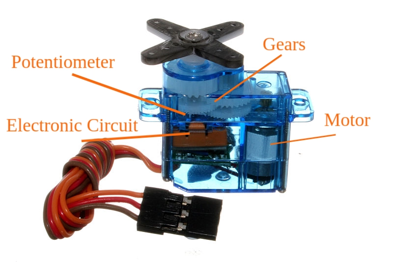 Figure 1: A labelled hobby servo motor. Image taken from here.)
Over the series of practicals in this course, you will build up a servo motor from its constituent parts, using a DC motor, a potentiometer to read the shaft position and an STM32 microcontroller to control the operation. Various analogue electronic circuits will be used to interface the microcontroller with the motor and potentiometer, and to control the power supplied to the motor. The figure below shows the hardware block diagram of the system.
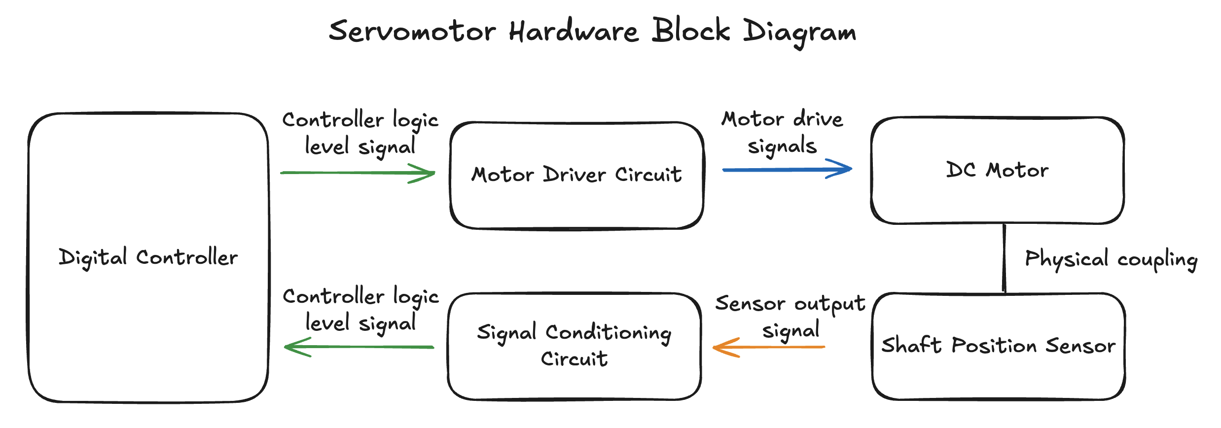 Figure 2: A block diagram representation of a servo motor.
In this practical we will use the knowledge you have gained from the previous practicals to build and control a servomotor from constituent parts. You will use a brushed DC motor and a feedback potentiometer as the elements of the servomotor. These will need to be driven with a appropriate H-Bridge and level adjusting circuitry. A position command signal will be generated using an onboard potentiometer from your UCT STM32 dev board. You will also be required to implement an already designed PI controller to control the position of the servomotor.
This practical is extensive and will require you to complete a number of tasks, building several circuits and writing a significant amount of code. Accordingly, this practical will run over the course of two weeks. During the first in-lab session you will be given a motor rig which contains the brushed DC motor coupled to a feedback potentiometer. This will need to be returned once you are ready to demonstrate your circuit during the second week.
Please use the feedback form to give us feedback on this practical and to report broken/faulty equipment.
Table of Contents
- The block diagram
- The motor rig
- Interface electronics
- Programming the STM32
- Demonstration and Submission
The block diagram
The hardware setup for this practical is shown in the following hardware block diagram:
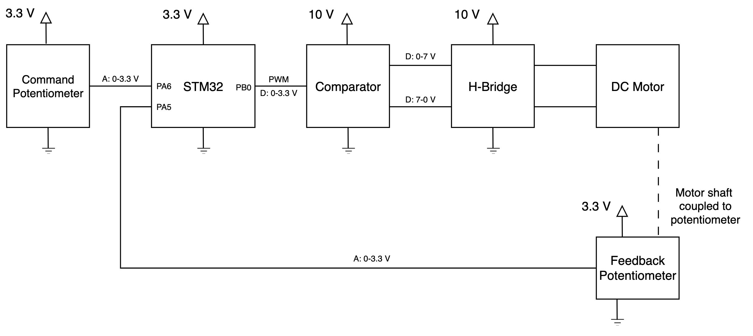
This figure shows the main components of the system:
- The STM32 microcontroller
- The comparator-based level-shifting circuit
- The H-Bridge
- The brushed DC motor
- The feedback potentiometer
- The position command potentiometer
Note that the 0-7 V range on the output of the comparator is an estimate of the output range likely to be seen when feeding the comparator supplies with 0-10 V, given that the output cannot be driven to the rails on the LM358.The brushed DC motor is driven by the H-Bridge circuit which is controlled by the STM32 microcontroller and level shifting circuitry. The position command signal is generated using the position command potentiometer. The feedback potentiometer is used to feedback the position of the motor to the STM32 microcontroller. This diagram also shows the power supply levels required for the various components in the system, and the number of and type of connections required between the components.
The STM32 microcontroller will be programmed using the standard STM32 programming template, and will need to perform the tasks shown in the diagram below:
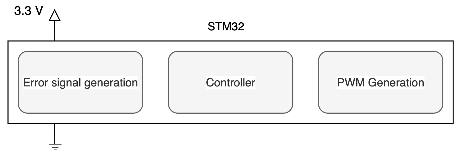
At a functional level, during the operation of the system, the STM32 needs to:
- Calculate the error between the position command signal and the feedback signal.
- Perform the PI control calculation.
- Output a control signal used to drive the H-Bridge and the motor.
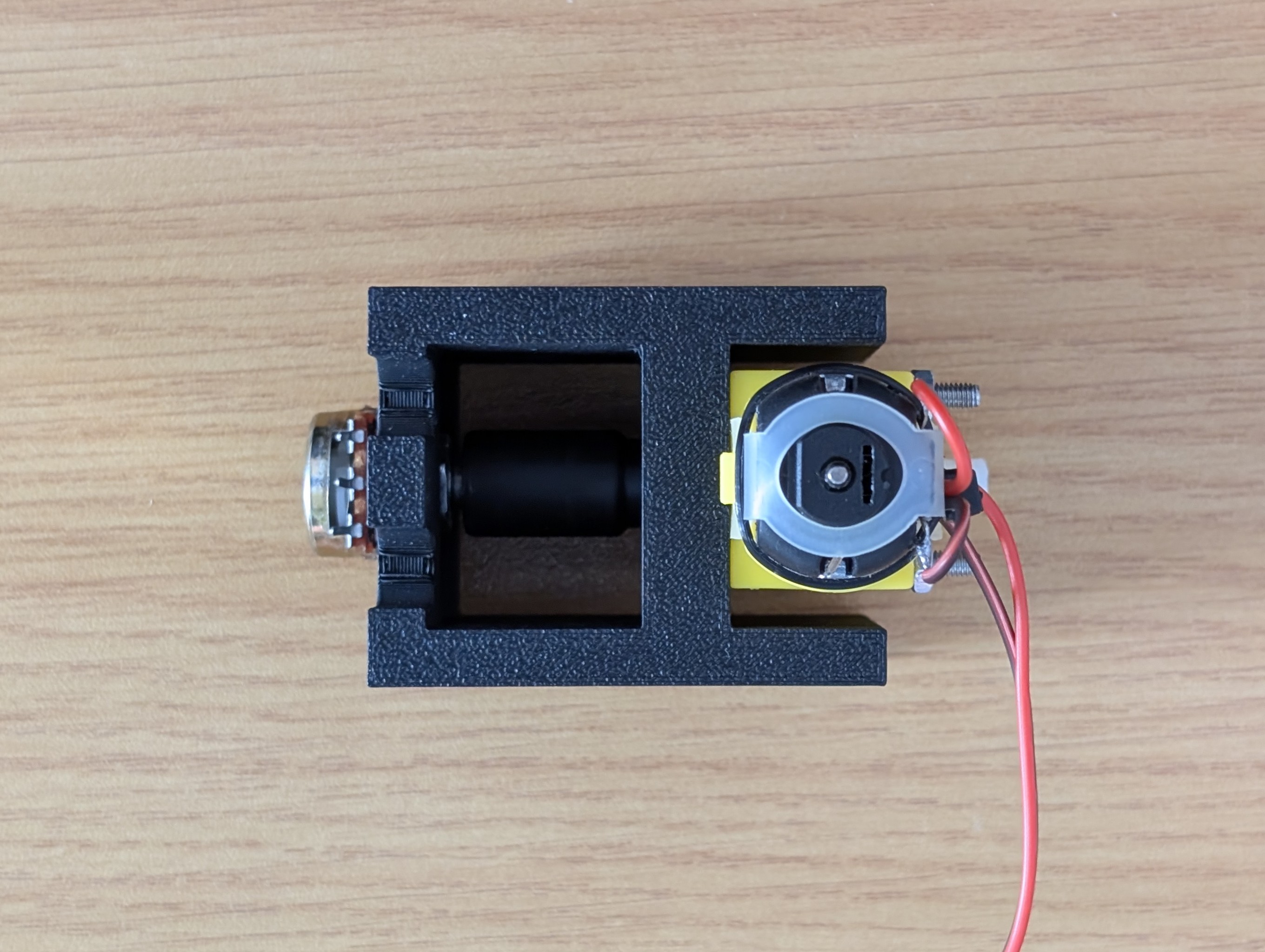
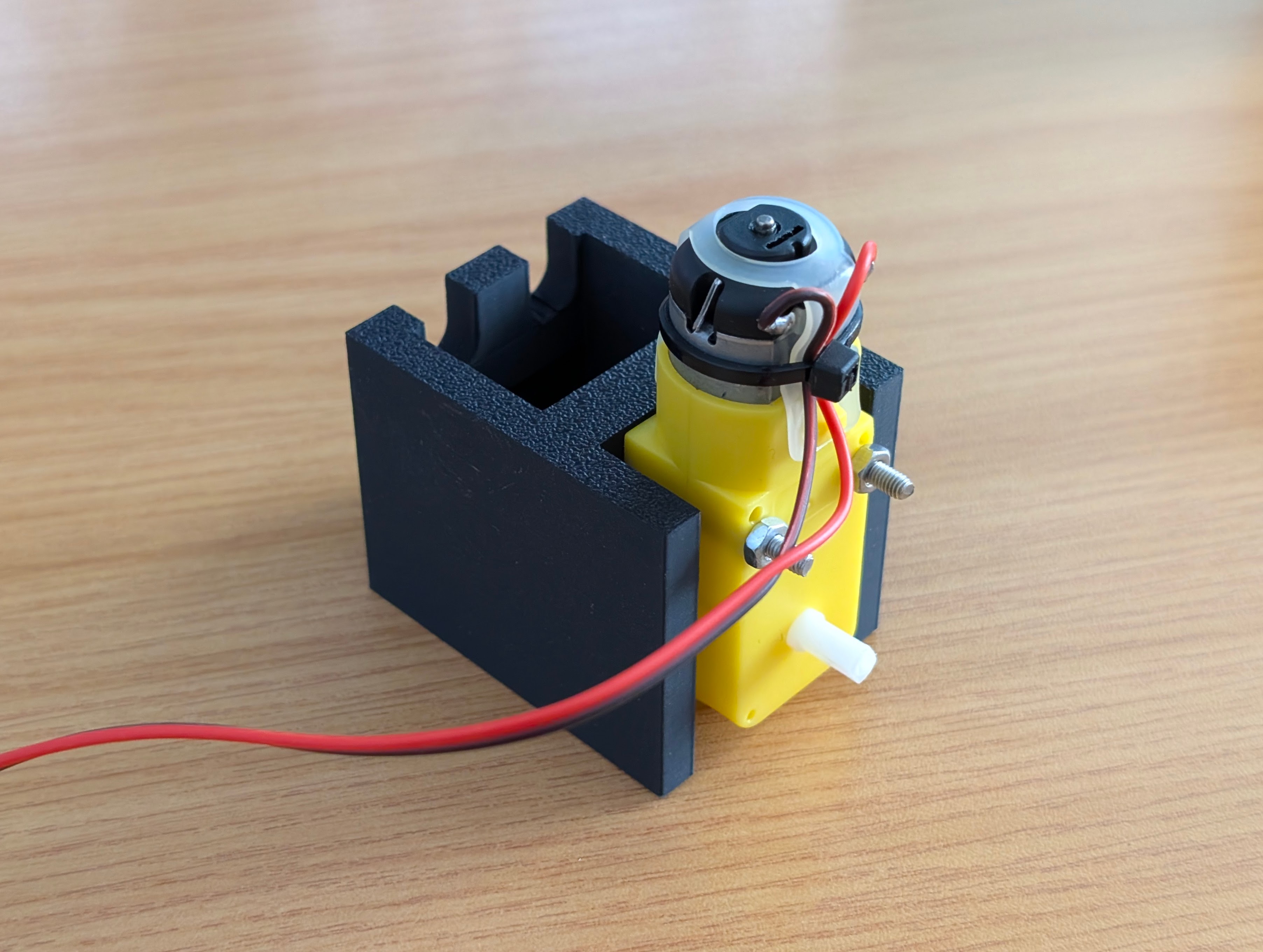
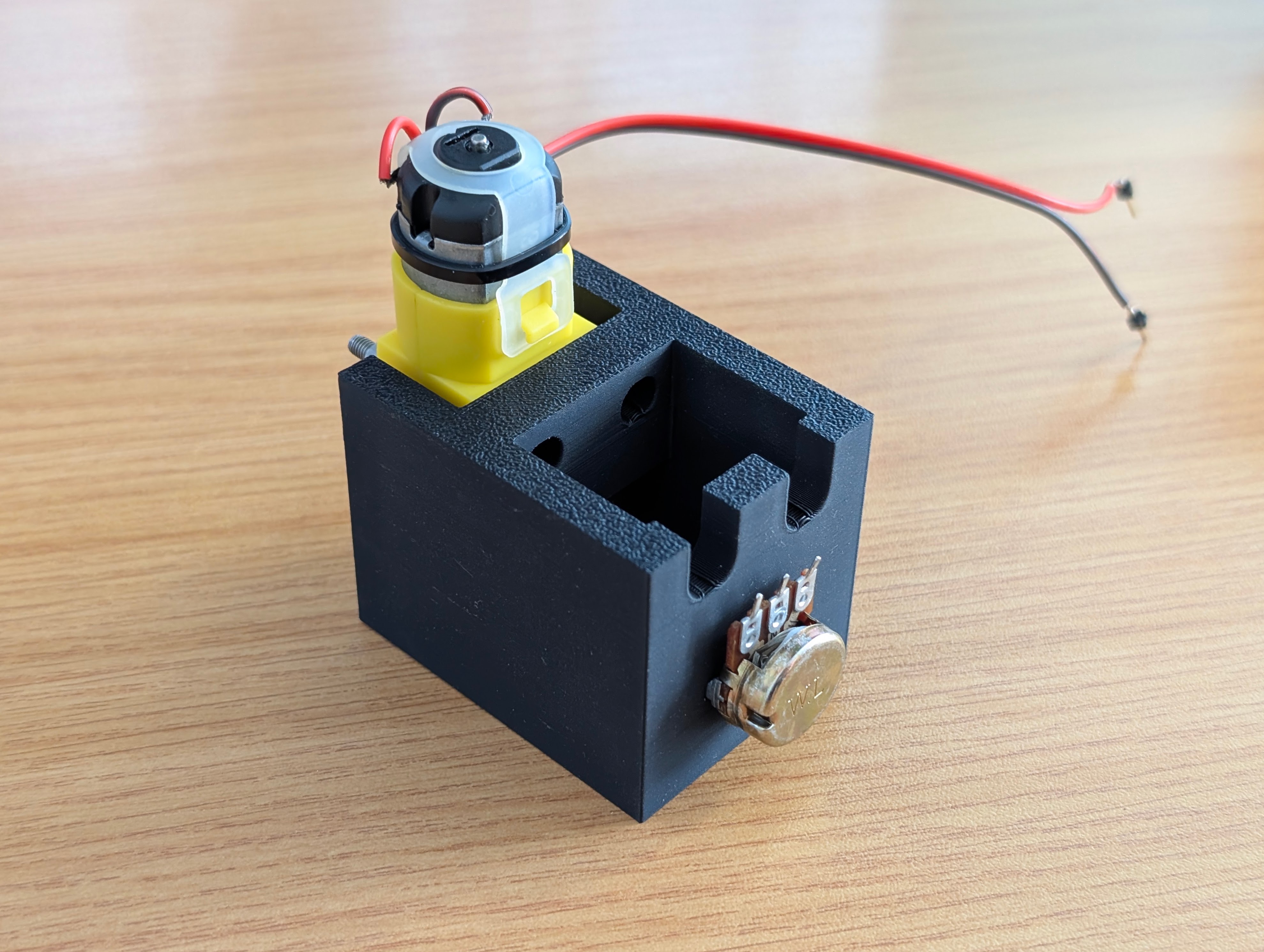
The motor rig
Each person will be given a motor rig during the first practical session. This rig is shown in the following figures:
Interface electronics
The interface electronics for this system should be designed to meet the following requirements:
- The STM32 microcontroller will generate a single PWM signal to drive the motor on PB4.
- The PWM signal should be converted into two anti-phase PWM signals to drive the H-Bridge and be of a voltage level compatible with the H-Bridge.
- A maximum voltage of 7 V may be applied across the motor terminals. This should be generated by the H-Bridge circuit which must take the form of an emmitter-follower type H-Bridge.
- The feedback potentiometer is connected to PA5. (Ensure that the potentiometer is appropriately labelled on your circuit diagram.)
- The position command potentiometer is connected to PA6. (Ensure that the potentiometer is appropriately labelled on your circuit diagram. Check the schemati for the UCT board if necessary.)
Question 1 [2 marks]
Draw a circuit diagram, based on the block diagram and the requirements above, of the interface electronics for the motor rig. Ensure that your circuit diagram includes all the components needed to build the drive electronics and that the circuit is compatible with the STM32 microcontroller. Ensure all supply voltages are appropriate for the components and functional requirements.
Question 2 [2 marks]
Using a table populated with parameters measured from your circuitry, demonstrate that your comparator-based level-shifting circuit works correctly.
Question 3 [2 marks]
Using a table populated with parameters measured from your circuitry, demonstrate that your H-Bridge circuit works correctly.
Programming the STM32
Using this template file, write the code needed to implement the measurement and control of the motor rig. Your code should implement the following functionality and be tracked in a git repository hosted on GitHub:
- Initialise the ADC to read the position command potentiometer on PA6 and feedback signal on PA5. The resolution of the ADC should be chosen such that a precision of 1 degree is achieved.
- Initialise the appropriate timer to generate a PWM signal to drive the motor from PB4. This signal should have a frequency of 20 kHz and an appropriate initial duty cycle. The configuration of the timer should be such that the result of the ADC conversions are matched in scale to the duty cycle control of the PWM signal.
-
Implement a PI controller to control the motor. The controller should take the form of an ideal PI controller with the following form:
$$ \frac{U(s)}{E(s)} = K_p \left(\frac{s+I}{s}\right) $$
where $K_p$ is the proportional gain and $I$ is the integral time constant. When converted to a discrete time domain implementation, the controller becomes:
$$ \frac{U(z)}{E(z)} = K_p \left(\frac{(2+IT_s)z + (IT_s-2)}{2z - 2}\right) $$
where $T_s$ is the sample time of the controller. Ensure that the controller is executed at a frequency of 1 kHz. Further, set
K_p = 50andI = 1. Implement the controller as a difference equation in a function calledPI_control(). You will need to choose an appropriate architecture for this function in terms of arguments and return values.If you are certain that your code and circuit work correctly but your system is unstable, you can try to tune the controller parameters to improve the system performance by lowering the proportional gain and/or the integral gain.
Question 4 [2 marks]
Plan and describe your code structure to implement the requirements above using a flowchart.
Question 5 [2 marks]
Implement your flowchart on the microcontroller and test that your servo-loop is operational and stable. Once ready, call a tutor to demonstrate it’s behaviour.
Question 6 [2 marks]
What effects do the proportional and integral gains have on the system? What effect does the sample time have on the system?
Question 7 [2 marks]
If your system is now operational and stable, commit your code with a commit message, “Q4 implemented”.
a) Now, using the LM358 datasheet, and introducing a new specification that the signal level change time on the drive signals of the H-Bridge must be less than 1% of the period of the PWM signal, determine the maximum frequency of the PWM signal that can be used. Calculate a new PSC value to implement this.
b) Update your program to implement this new specification and commit your code with a commit message, “Q5 implemented” once complete. What do you observe about the system performance? Measure the signal level change time and the period and frequency of the PWM signal in your answer. Do they match the calculated values?
Demonstration and Submission
By demonstrating and submitting this practical you agree that:
- You know that plagiarism is a serious form of academic dishonesty.
- You have read the document about avoiding plagiarism, are familiar with its contents and have avoided all forms of plagiarism mentioned there.
- Where you have used the words of others, you have indicated this by the use of quotation marks.
- You have referenced all quotations and other ideas borrowed from others.
- You have not and shall not allow others to plagiarise your work.
- You have not used an AI language model to generate the code submitted without attributing the fact in your code.
Before your demonstration ensure that you are ready to show your answers to the above questions to a tutor.
When you are ready to demonstrate, call over tutor. You will then be asked to show your answers to the questions above and demonstrate them. Then run your C code on a UCT STM32 Dev board. The tutor will then assign a mark as described by the marks above.